



 EN
EN  FR
FR  ES
ES  PT
PT  RU
RU  FA
FA Pressure Relief Valve
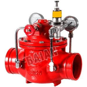
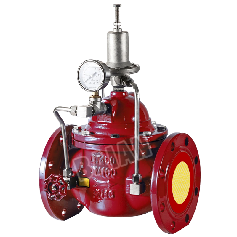
The Flange Pressure Relief Valve by BAIAN is pilot-controlled, designed to automatically relieve excess pressure in fire protection systems, maintain steady discharge pressure, offer adjustable settings, and features a max 16 bar pressure with epoxy coating.
See the Pressure Relief Valve Catalog for more!
Flange Pressure Relief Valve
PRODUCT DESCRIPTION
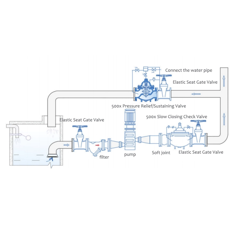
BAIAN brand Pressure Relief Valve is designed specifically to automatically relieve excess pressure in fire protection pumping system .Pilot controlled ,it maintains constant system pressure at the pump discharge within very close limits as demands change.
FEATURES
1.Fast Opening to Maintain Steady Line Pressure
2.Accommodates Wide Range of Flow Rates
3.Closes gradually for surge- free operation
4.Adjustable Pressure Settings ,Not Affected by Pressure at Valve Discharge
WORKING PRESSURE
Maximum working pressure 16 bar (230psi)
STANDARD
Product testing is carried out in accordance with GB/T13927 Industrial valve pressure test
SET PRESSURE
Factory pre-set outlet pressure to 10 bar (144psi)
TEMPERATURE RANGE
0 °C to 80°C
COATING
Fusion Bonded Epoxy Coating
OPERATION REQUIREMENTS
1.A filter must be installed before the pressure relief pressure holding valve
2.When adjusting, the screw on the pilot valve should be withdrawn, the water pump should be started to let water out of the pressure relief valve, and the adjusting screw should be gradually screwed in to gradually increase the pressure until the pressure to be set is reached. After adjustment, tighten the locking nut.



Leave Your Message